

SEO Title: Centrifugal Fan Duty Point Engineering Guide Meta Description: Engineering guide to centrifugal fan system resistance, duty-point validation, airflow testing, operating margins, system effects, and failure analysis. Target Keyword: centrifugal fan Secondary Keywords: fan duty point, system resistance curve, centrifugal fan performance, airflow validation, fan system effects URL Slug: centrifugal-fan-system-resistance-duty-pointCentrifugal Fan Working Principles, Failure Mechanisms, and Engineering Specifications: System Resistance and Duty Point
A centrifugal fan can meet its factory curve yet fail to deliver required airflow after installation because elbows, filters, dampers, inlet distortion, leakage, and gas-density changes shift the operating point. This article explains how engineers should connect the fan curve to the system curve, validate real duty conditions, control unstable operation, and specify evidence without treating maximum airflow or pressure as a usable design point.
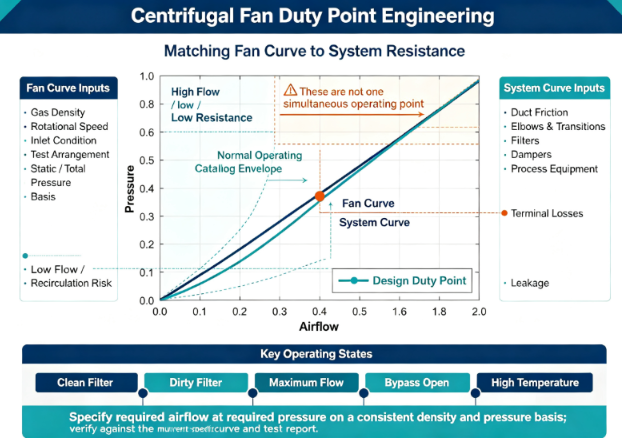
Air enters the impeller near the shaft axis. Rotating blades increase the fluid's angular momentum and velocity, while the casing and discharge geometry convert part of that velocity into static pressure. The motor supplies shaft power, the impeller transfers energy to the gas, and the duct system consumes that energy through friction, fittings, filters, process equipment, elevation effects where relevant, and terminal losses. The installed airflow settles where the fan pressure capability and system resistance are equal.
The fan curve is not a single rating. It is a relationship among airflow, static or total pressure, shaft power, efficiency, and often sound or speed at a stated gas density, rotational speed, inlet condition, and test arrangement. The system curve is also conditional. For a fixed clean-air network dominated by turbulent losses, pressure loss often changes approximately with the square of flow, but filters, dampers, process hoods, stacks, temperature, leakage, variable branches, and material loading can alter that relationship. The specification should therefore define the complete operating envelope rather than one nominal point.
At the design duty, the selected centrifugal fan needs enough margin to accommodate credible resistance growth without moving into an unstable or inefficient region. Excessive margin is not automatically safer. A fan selected far from its efficient region can consume unnecessary power, create high velocity and noise, require throttling, or overload the motor when the system resistance changes. A duty-point review should examine normal, clean-filter, dirty-filter, startup, minimum-flow, maximum-flow, bypass, emergency, high-temperature, and altered-density conditions.
Gas density connects temperature, pressure, composition, and altitude to fan performance. A volumetric airflow may remain similar at a given speed while mass flow and pressure capability change with density. Motor power demand also changes. Corrections must use the actual inlet state and verified performance method. A generic site-temperature or altitude note is insufficient when the process gas is hot, humid, solvent-laden, dust-bearing, or chemically different from standard air.
No technical standard or verified performance appendix was supplied for this article. Therefore, no test standard, tolerance, certificate, airflow, pressure, efficiency, noise, temperature, speed, or power value is claimed; verify each parameter against the manufacturer's current model-specific test report before specification.
Under stress or failure, the operating point can move quickly. A blocked filter raises resistance and reduces flow; an opened bypass lowers resistance and can increase motor load; a damaged duct can add leakage; a coating process can foul blades and reduce pressure; a high-temperature excursion changes density and material condition; a closed damper can force the fan toward low-flow recirculation. Protection should monitor variables that reveal the actual state, not assume that motor speed alone proves airflow.
The aerodynamic and mechanical assembly must be evaluated as one system. Material grades and numeric limits were not provided, so each field below is a verification requirement. The selected construction should reflect gas composition, temperature, particulate loading, corrosion, cleaning method, rotational stress, and required service access.
| Component | Material Spec | Function | Performance Parameter | Failure Risk if Compromised |
|---|---|---|---|---|
| Impeller and blades | Verify base material, thickness, weld procedure, coating, corrosion allowance, hub attachment, and temperature derating. | Transfer shaft energy to the gas and establish the pressure-flow characteristic. | Verify diameter, blade geometry, speed limit, balance condition, efficiency, pressure, flow, and fouling tolerance. | Loss of pressure, unstable flow, vibration, erosion, fatigue cracking, or fragment release. |
| Inlet, cone, and casing | Verify sheet or casting material, thickness, reinforcement, surface protection, joint construction, and leakage class. | Guide inlet flow, recover pressure, contain the rotating assembly, and direct discharge. | Verify inlet clearance, geometry, casing pressure, leakage, deformation, and connection loads. | Inlet recirculation, reduced efficiency, rubbing, leakage, casing fatigue, or distorted curve. |
| Shaft, bearings, and coupling or belt drive | Verify shaft material, bearing type, lubricant, coupling or belt specification, guards, and thermal separation. | Transmit torque while maintaining impeller position through operating and transient loads. | Verify critical-speed margin, bearing life, alignment, temperature, runout, belt tension, and allowable loads. | Misalignment, heat, vibration, belt slip, bearing failure, or shaft fatigue. |
| Motor and speed-control system | Verify motor construction, insulation, enclosure, cooling, cable, drive compatibility, and grounding. | Supply torque across startup, duty changes, turndown, and fault response. | Verify power, torque, current, speed range, cooling, acceleration, protection, and harmonic effects. | Overload, overheating, nuisance trip, insufficient acceleration, or unsafe overspeed. |
| Duct, damper, filter, and flexible connection | Verify duct material, liner, seal, damper construction, filter medium, support, and connector compatibility. | Create the installed system resistance and isolate or regulate process flow. | Verify pressure loss, leakage, damper authority, filter loading, stiffness, and system-effect allowance. | Wrong duty point, inlet distortion, vibration transfer, leakage, or unstable branch flow. |
| Instrumentation and protection | Verify pressure taps, flow sensors, temperature sensors, vibration sensors, tubing, wiring, and enclosure. | Measure actual operation and detect deviation, fouling, blockage, overload, and mechanical deterioration. | Verify range, accuracy, location, calibration, alarm logic, delay, and data retention. | False assurance, missed blockage, incorrect control, delayed trip, or poor root-cause evidence. |
Verify all parameters against current test reports and applicable standards before use in specifications.
The evidence package should identify whether pressure is static, velocity, or total pressure; where it is measured; how airflow is determined; which gas state is used; and how instruments are calibrated. Maximum catalog values from different locations on a curve cannot be combined into one duty point. With no technical standard supplied, the test method and acceptable ranges must be defined in the project protocol and verified in current model-specific reports.
| Parameter | Standard | Test Method | Acceptable Range | Implication if Out of Range |
|---|---|---|---|---|
| Airflow at required pressure | No technical standard supplied. | Measure airflow and pressure simultaneously with calibrated instruments at the stated speed, density, inlet condition, and system configuration. | Verify project tolerance and model-specific result against the current approved report. | The process may lack capture velocity, cooling, drying, combustion air, or ventilation capacity. |
| Efficiency and input power | No technical standard supplied. | Record electrical input, motor behavior, shaft or verified drive losses, airflow, and pressure across the required envelope. | Verify the calculation boundary, tolerance, and acceptance range before specification. | Energy use, motor sizing, heat release, and operating cost assumptions become unreliable. |
| System-effect loss | No technical standard supplied. | Compare a controlled inlet and discharge arrangement with the actual elbow, transition, damper, guard, plenum, and duct configuration. | Verify allowable loss in the project aerodynamic model and commissioning report. | Installed performance can fall below the factory curve despite a conforming fan. |
| Stable operating range | No technical standard supplied. | Traverse flow from minimum to maximum while recording pressure pulsation, current, vibration, sound, temperature, and control stability. | Verify prohibited and permitted regions from current manufacturer evidence. | Rotating stall, recirculation, pulsation, fatigue, and process instability can occur. |
| Filter-loading and branch variation | No technical standard supplied. | Simulate clean and loaded filters, damper positions, branch closures, and leakage states; plot resulting duty points. | Verify that every required state remains within approved motor, stability, and process boundaries. | Flow can become inadequate in one branch or overload equipment in another. |
| Site acceptance correlation | No technical standard supplied. | Measure installed flow, pressure, speed, current, temperature, vibration, and process state and reconcile them with the approved curve and system model. | Verify project-specific correlation limits and measurement uncertainty. | Factory evidence cannot be connected to actual system performance. |
Verify all parameters against current test reports and applicable standards before use in specifications.
In our field testing, the most useful record is a synchronized operating map, not one airflow reading. It should include fan speed, inlet and outlet pressure, gas temperature, relevant humidity or composition, motor current and power, damper position, filter differential pressure, branch state, vibration, and process load. The report should document pressure-tap locations, straight lengths, flow profile, leakage, instrument uncertainty, stabilization time, and data filtering.
The first protection mechanism is correct system matching. The fan curve and system curve should be placed on the same basis, including density, pressure definition, speed, and geometry. Duct friction, elbows, transitions, filters, valves, silencers, process equipment, stacks, and terminal losses must be combined. Inlet swirl or nonuniform velocity can reduce pressure and efficiency even when calculated resistance is correct. Discharge elbows placed too close to the casing can interfere with velocity recovery. The engineering record should state the duty point, tolerance, margin, clean and loaded conditions, system-effect allowance, and field method used to verify flow and pressure.
Operating stability protects both process and machine. At low flow, internal recirculation and rotating stall can create pressure pulsations and cyclic blade loading. At low system resistance, airflow and motor demand may rise beyond the selected operating boundary. A speed controller can move the curve, but it does not eliminate unstable regions or incorrect sensing. Control logic should use a pressure or flow signal located where it represents the process, apply validated limits and ramp rates, and define behavior after sensor loss. Damper and speed control should not fight each other through independent loops.
High-temperature, dusty, wet, and corrosive gases change the physical boundary. Density corrections alone do not address material strength reduction, differential thermal expansion, bearing temperature, lubricant life, coating resistance, dew point, condensation, particle erosion, buildup, or chemical attack. Specification inputs should include continuous and transient gas temperature, composition, humidity, dew point, particulate concentration, size distribution, abrasiveness, stickiness, corrosivity, and cleaning method. Those inputs should drive material, thickness, corrosion allowance, shaft seal, bearing isolation, cooling, drainage, access, and inspection decisions.
Mechanical integrity protects the pressure boundary and rotating assembly. The impeller experiences centrifugal stress, aerodynamic bending, cyclic loading from flow nonuniformity, residual welding stress, thermal gradients, and mass imbalance caused by manufacturing tolerance or deposits. A credible validation chain connects stress analysis, material properties at temperature, weld control, overspeed evidence, balance, runout, assembled vibration, bearing temperature, critical-speed separation, and endurance. Public statements about high-speed, aging, or vibration tests are incomplete unless speed, duration, sample configuration, instrumentation, acceptance criteria, and before-and-after results are disclosed.
Electrical and ignition protection must be configuration-specific. A generic explosion-proof label cannot establish suitability for a hazardous gas or dust location. The engineer needs the classified environment, gas or dust group, temperature limitation, equipment marking, certificate scope, motor and drive pairing, enclosure, cable entries, bonding, grounding, static control, hot-surface analysis, and measures against impeller-to-casing contact. Because no technical standard or verified certificate was supplied, all such claims and markings require confirmation from the current certificate and product documentation before specification.
Variable-frequency operation introduces a broader mechanical envelope. Reducing speed changes airflow, pressure, and power, but it can also reduce motor cooling, move excitation through structural resonances, alter bearing and belt behavior, and create electrical stress. Minimum stable speed, maximum permitted speed, acceleration, deceleration, prohibited frequency bands, control-loop tuning, overspeed prevention, motor thermal protection, and fault interlocks require model-specific verification. A fan law calculation should not be used outside a validated similarity range or as a substitute for a measured curve.
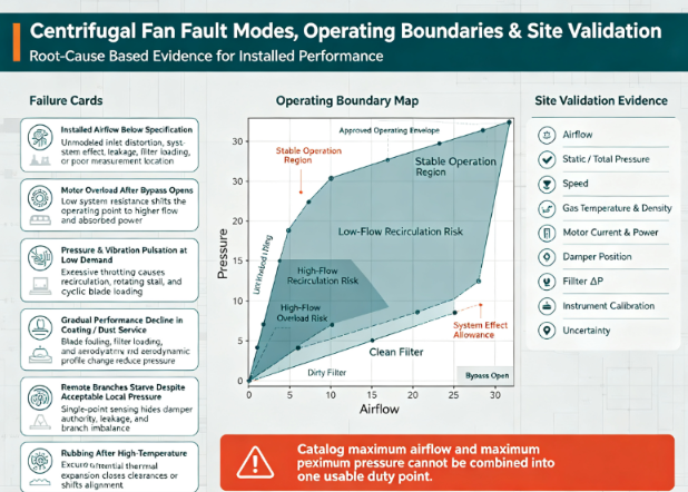
Instrumentation closes the protection loop. Filter differential pressure helps identify loading, but it cannot prove flow when duct configuration changes. Motor current can reveal overload, but low current can mean low density, low flow, belt slip, or impeller damage. Vibration can reveal imbalance or looseness, but sensor location and frequency content matter. Protection should combine measurements, plausibility checks, alarm delays, trip logic, and trend limits derived from the verified operating map.
Failure: installed airflow is below the specified value. The root cause may be an unmodeled inlet elbow, undersized transition, loaded filter, closed damper, duct leakage, or pressure measurement taken at a location with strong velocity distortion. The consequence is inadequate capture, drying, cooling, or ventilation even though the fan reaches rated speed. Prevention requires a complete system resistance model, system-effect allowance, defined measurement planes, commissioning traverse, and correction of the duct geometry rather than an arbitrary speed increase.
Failure: the motor overloads after a bypass opens. Lower system resistance moves the operating point to higher flow and can increase absorbed power for the selected impeller type. The control system may protect pressure but fail to limit motor current. Consequences include thermal trip, accelerated insulation aging, or process interruption. Prevention requires evaluation of minimum-resistance states, power across the full curve, motor and drive limits, and a validated current or flow constraint.
Failure: pressure and vibration pulsate at low demand. Excessive throttling can force the fan into recirculation or rotating stall. Periodic aerodynamic loading excites the casing, duct, and impeller, producing noise and fatigue. Prevention requires identification of the stable operating boundary, minimum-flow control, suitable fan sizing, coordinated speed and damper logic, and time-resolved pressure and vibration testing.
Failure: performance declines gradually in a coating or dust process. Sticky material deposits on the blade alter the aerodynamic profile and add uneven mass, while filter loading shifts the system curve. Pressure falls, current and vibration may change, and the process loses uniformity. Prevention requires fouling assessment, appropriate blade and coating selection, cleaning access, differential-pressure and vibration trending, and a maintenance trigger based on measured condition.
Failure: field pressure appears acceptable but remote branches starve. A single pressure sensor near the fan can remain on target while dampers, leakage, or branch resistance redistribute flow. The control loop satisfies the local signal rather than the process requirement. Prevention requires branch balancing, representative sensing, verified damper authority, flow measurement at critical users, and fault logic for implausible branch states.
Failure: a high-temperature excursion causes rubbing. Unequal thermal expansion of the impeller, shaft, casing, supports, and inlet cone can close running clearance or shift alignment. Contact adds heat and can generate sparks or severe vibration. Prevention requires transient temperature cases, material-expansion analysis, hot alignment, verified clearances, bearing and support design, temperature monitoring, and controlled shutdown criteria.
Define casing pressure, vacuum, nozzle loads, support reactions, thermal expansion, transport, seismic or wind conditions where applicable, and maintenance loads.
Require impeller stress, shaft deflection, critical-speed separation, balance, runout, bearing life, weld quality, casing stiffness, and fatigue evidence.
Specify allowable connection loads, flexible-joint function, base stiffness, anchorage, alignment, guarding, and service clearances.
Verify all material grades, thicknesses, coatings, fasteners, weld procedures, and temperature derating against current controlled documents.
Define normal, minimum, maximum, startup, shutdown, clean-filter, dirty-filter, bypass, branch-change, and emergency duty points.
Require full curves for airflow, pressure, efficiency, absorbed power, speed, sound, and permitted operating region on a consistent gas-density basis.
Specify motor torque and power margin, drive type, belt or coupling behavior, speed range, ramps, prohibited frequencies, cooling, overspeed protection, and fault response.
Require the delivered fan, motor, drive, impeller, software or parameters, and curve identification to be traceable as one configuration.
State gas composition, continuous and transient temperature, humidity, dew point, density, altitude, particulate concentration, particle size, abrasiveness, stickiness, and corrosivity.
Define indoor or outdoor exposure, rain, dust, washdown, salt, ambient temperature, ventilation, condensation, and storage conditions.
Specify cleaning method, drainability, access, coating repair, inspection intervals, and disposal or containment of hazardous deposits.
Verify enclosure, ingress, corrosion, temperature, hazardous-location, and acoustic claims from current model-specific evidence.
No technical standard was supplied; verify every proposed standard, edition, clause, certificate, scope, issuing body, and model coverage before specification.
Require a model-specific hazard analysis covering rotation, entanglement, fragment containment, hot surfaces, pressure, noise, vibration, electricity, ignition, chemicals, and maintenance access.
Require calibrated test records, raw data, uncertainty, specimen configuration, curve basis, acceptance criteria, deviations, approvals, and traceability to the delivered unit.
Require commissioning evidence that reconciles the factory curve, system model, site measurements, control states, and process acceptance.
Zhejiang Shangyang Industrial Fan Co., Ltd. reports twenty years of engineering, manufacturing, and sales experience, standard and nonstandard fan capability, continued product development, specialized test reports, and application experience across coating, kilns, boilers, dust collection, environmental systems, printing, chemical processing, and food production. Evaluate any manufacturer by whether it can translate process data into a verified duty envelope, provide controlled curves and drawings, demonstrate mechanical integrity and material compatibility, manage configuration changes, support field testing, and investigate deviations with traceable evidence.
They usually occur at different locations on the fan curve and do not describe one simultaneous operating condition. Specify the required airflow at the required pressure, together with gas density, speed, power, efficiency, and operating limits. Verify the point against the current model-specific curve and test report.
Model the resistance at the defined terminal filter condition and plot that system curve against the fan curve. Confirm process flow, motor load, efficiency, and stability at both clean and loaded states. The filter replacement trigger should connect differential pressure to verified airflow rather than rely on a generic schedule.
No; they are useful estimates only when geometry, gas behavior, and aerodynamic similarity remain valid. System effects, motor and drive efficiency, Reynolds effects, unstable regions, and mechanical limits can invalidate a simple extrapolation. Verify the revised operating envelope with current manufacturer data and, when required, model-specific testing.
Measure airflow, relevant static or total pressures, speed, gas temperature and density inputs, motor current and power, damper position, and filter condition at documented locations. Include vibration and bearing temperature to confirm mechanical condition. State instrument calibration, uncertainty, stabilization time, and duct geometry.
Provide sufficient straight and uniform approach flow or use an engineered inlet arrangement whose effect has been validated. Elbows, screens, guards, dampers, and asymmetric plenums near the inlet can change pressure, power, noise, and vibration. Compare the proposed installation with the test arrangement and include a verified system-effect allowance.
Internal Link Suggestions Anchor Text | Insert Location | Target Page Type centrifugal fan performance curve | H2 1 after operating-point explanation | Fan selection engineering guide industrial fan system resistance calculation | H2 4 after system-matching paragraph | Technical calculation article high-temperature centrifugal fan design | H2 4 after material-boundary paragraph | High-temperature product category centrifugal fan vibration analysis | H2 5 after low-flow pulsation failure | Mechanical reliability article centrifugal fan technical specifications | H2 7 after manufacturer evaluation | Product page with verified model data
Este site usa cookies para garantir que você tenha a melhor experiência em nosso site.
 EN
EN Español
 Pусский
 Français
 Deutsch
 日本語
日本語 한국어
한국어 العربية
 ไทย
ไทย हिन्दी
 Tiếng Việt


Comente
(0)